AutoLoader 2.x Components
The AutoLoader 2.x consists of the components listed in the following table.
For information about the components of an iScan system, refer to the iScan System Product Documentation (document # 1000000161301).
|
Name |
Description |
|---|---|
|
Base Plate |
The base plate holds the AutoLoader 2.x components in precise positions, so that the robot can move the BeadChip carriers successfully. Do not move the base plate. |
|
Robot Housing |
The robot housing provides a stable base for the robot arm. |
|
Robot Arm |
The robot arm moves the BeadChip carriers between locations. |
|
Gripper |
The gripper grasps the sides of the BeadChip carrier and lifts and moves it between the stacks and the reader tray(s). |
|
Input Stack |
The input stack holds carriers with BeadChips that are ready to be scanned. By default, the two leftmost stacks are input stacks. |
|
Output Stack |
The output stack holds carriers containing BeadChips that have scanned without errors, or with fewer errors than the error threshold. By default, the third and fourth stacks are the output stacks. |
|
Error Stack |
The error stack is a specialized output stack that allows for easy identification of BeadChips with scan errors. The error stack holds carriers that resulted in system errors or contain BeadChips that crossed the error threshold. |
|
BeadChip Carrier |
The BeadChip carrier holds up to four BeadChips. Each carrier acts as a lid for the carrier beneath it (shown inside stack extrusions). |
|
Lid |
The lid protects the BeadChips in the top carrier in a stack from exposure to excessive light, heat, and humidity. |
|
Lid Stack |
The lid stack holds lids while they are not on an input, output, or error stack. |
|
DB–9 Switchbox |
The switchbox enables you to change which reader is the local reader and which is the remote reader by flipping a switch. |
|
Stack Extrusion (not shown) |
The extrusion keeps the stacked carriers in place so that the robot arm can lift and replace them successfully. |
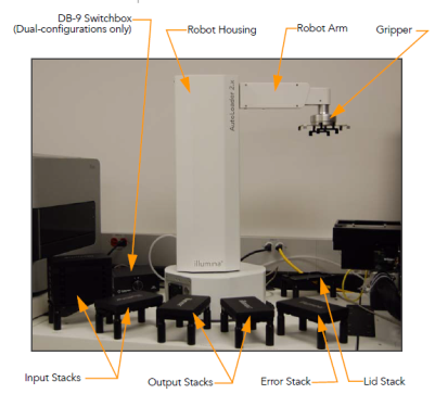
The following figure shows the AutoLoader 2.x component locations.